English


A chain is only as strong as its weakest link…
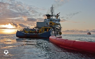
Oil spill incidents are unplanned and unwanted events that can have dire consequences for the environment and fragile ecosystems around the globe. Fast response combined with the correct equipment able to cope with any type of hydrocarbon emulsion is vital to minimize the risk involved in extracting, processing and transporting petrochemicals outside our coastlines.
Parat Halvorsen, in close cooperation with yards and ship owners, has developed a system that strengthens one vital part of the response value-chain in a very cost efficient way. A heating system that is fully integrated into the response vessels utility and heat recovery loop - and that in moments can be re-mobilized to deliver steam through specially engineered injection nozzles into the tanks that carry recovered hydrocarbons.
PARAT Halvorsen is a Norwegian technology company providing state of the art solutions for steam- or other heated medium based processes. PARAT has delivered boilers and heaters to the marine and offshore markets since 1970.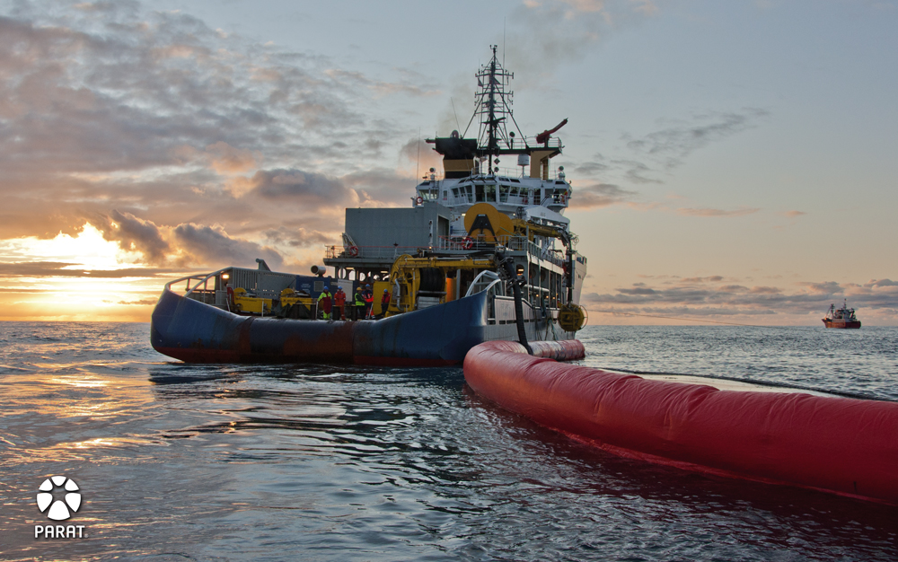
Theory
Exploration and production of hydrocarbons off coast-lines around the world is increasing. Reliable oil spill response solutions are essential, and the focus on this type of technology is constantly growing.
PARAT has been working on the transportation aspects of this problem for years now. Ships store the oil recovered from the sea in tanks, and the oil needs to stay viscous so the tanks can be emptied. This is done by injecting steam into the emulsion during transport.
During the Prestige oil spill incident in the Bay of Biscay in 2002 it was discovered that the recovered oil settled quickly in the storage tanks and became too thick to be pumpable. The only way to get it out was mechanically. In order to increase the viscosity, steam was injected directly into the tanks.
In the aftermath, NOFO (Norwegian Clean Seas Asso-ciation for Operating Companies), developed a basic standard for vessels to be approved for oil spill recovery operations which specifically requires tank heating to be part of the vessels basic equipment.
When presented with such an opportunity, PARAT Halvorsen worked closely together with the yards and owners to find and develop the most space and cost efficient solution available. This involves integrating the vessel hot water loop with the contingency steam injection tank heating system.
Various basic concepts :
 |
Steam backup - dedicated steam boiler installed as a 100% backup system, which will only be in operation when the vessel is in Oil Recovery mode. |
 |
Steam boiler with two phase heat exchanger - steam boiler provides heat to the vessels hot water loop through a steam/hot water heat exchanger. In Oil Recovery mode, a small flow is still routed through the heat exchanger to provide sufficient heat for the critical HVAC consumers. |
 |
Combined steam and hot water boiler - boiler fully integrated in the vessel hot water and heat recovery loop. When in Oil Recovery mode the boiler is dedicated to supply steam for tank heating, and the HVAC-loop is maintained with a bypass system. The system is patented by PARAT Halvorsen. |
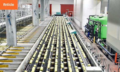
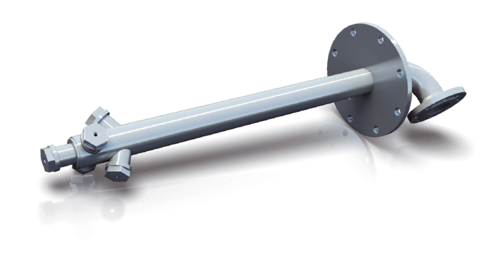
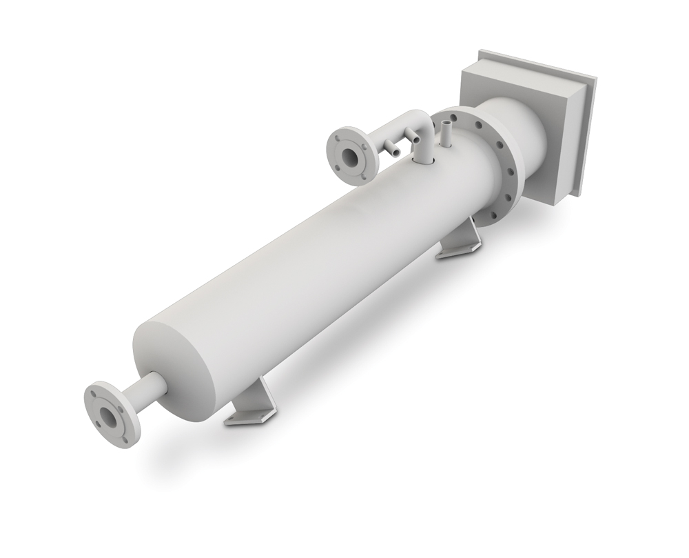
Multi nozzle lance
In case of oil pollution to the sea surface, the oil will be recovered and stored in tanks in the oil recovery ships until it can be delivered for processing. Experience from such situations has shown that the oil must be heated to maintain a sufficient viscosity for offloading. To ensure that the recovery vessels can operate efficiently, NOFO has made regulations requiring a sufficient heating system for the tanks on board. Presently, such oil tanks are heated by steam from a boiler on board. The steam is in many cases delivered to several nozzles installed around the perimeter of the tank. To achieve an adequate distribution of steam and heat in the tank multiple nozzles must be installed.
Such an installation has several drawbacks. One is the necessity of many openings in the tank. Another is the need of a manifold to distribute the steam. Both these features lead to a lot of couplings and gaskets that may develop leaks, and which are costly. Even with several nozzles installed, the heat distribution may be insufficient, leaving spaces such as the area around the tank outlet in the bottom in a cold shadow. There may also be insufficient space around the tank for such a large installation. Often the tank is accessible only in a small sector of its circumference, making it difficult to provide a sufficient number of steam inlets. PARAT Halvorsen has developed a multi nozzle arrangement that ensures a better distribution of heat in the oil recovery tank and at a lower cost than previously mentioned alternatives. This is achieved with a distribution system which is capable of heating the whole tank from one insertion point. The arrangement reduces the need for complicated assemblies in the tanks, and also ensures that it is sufficient with one nozzle system per tank. ︎
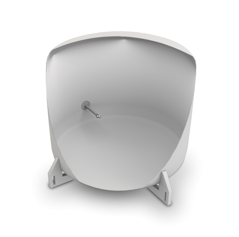
Permanent installation
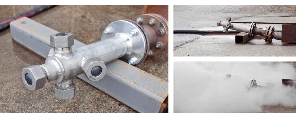
The multi nozzle steam lance will be designed and optimized for each tank. For tanks where entrance is not allowed, the lance must be installed permanently. To enable permanent installation the nozzle heads are fitted with rupture discs that ensure that there will be no ingress of pollution to the nozzle head when the lance is not in operation.
Integrated Solution
To save space, cost and to ensure proper functioning of the boiler equipment, it is smart to ensure that the boiler is in constant operation and part of the overall vessel HVAC system. PARAT Halvorsen has solved this as illustrated above. 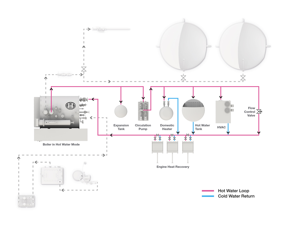
Normal operation:
During normal operation the boiler is part of the vessel hot water loop. When the heat demand is higher than the heat recovered from the engines, the boiler will start and supply the additional energy required.
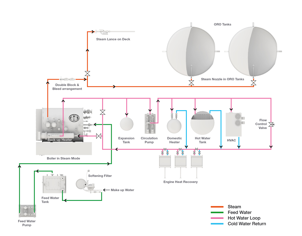
Oil recovery mode:
If an emergency should occur, the boiler is isolated from the hot water loop. Heating for critical HVAC consumers is maintained by a compact back-up heater. The water level is lowered and the boiler is switched to steam mode. Steam is then supplied directly to the tanks that contain recovered oil.
Tank Heating Solutions
for Oil Spill Response Vessels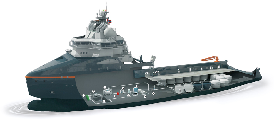
1. Boiler with Back-up heater 2. Water Treatment System 3. Engine Heat Recovery 4. Feedwater Pump 5. Expansion Tank 6. Circulation Pumps 7. Domestic Heater 8. Tank Heating 9. HVAC 10. Block & Bleed System 11. Multi Nozzle Steam Lance 12. Hand Held steam lance
|
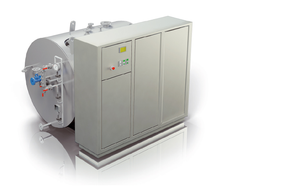
The Combined steam and hot water boiler, which is patented by PARAT Halvorsen, is in daily use as it is fully integrated in the vessels hot water loop. Typical duty: 1250kW |
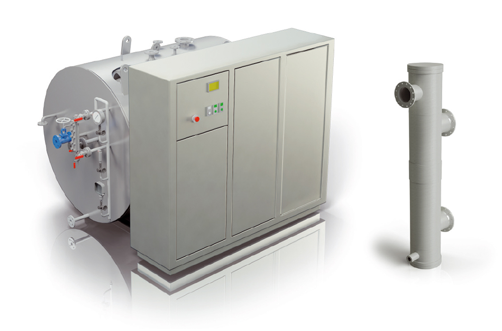
 |
When steam is required for tank heating, a small back-up heater keeps up the temperature in the hot water loop. Typical duty: 200kW. The heater is normally placed on top of the boiler. |
 |
The multi nozzle steam lance is installed through a flange connection in the tank, and should be installed as close to the tank suction outlet as possible. |
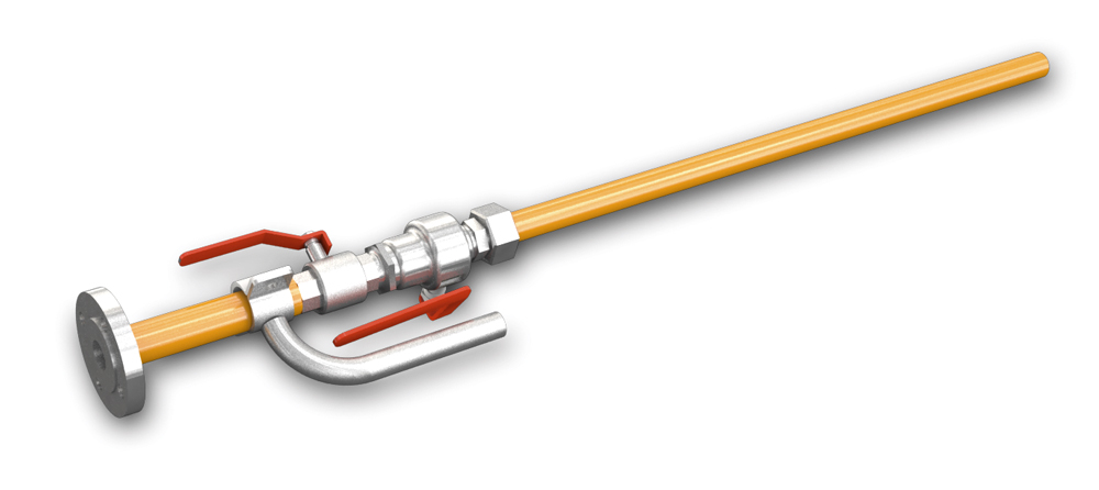 |
PARAT Halvorsen has developed a handheld steam lance for connection to a steam outlet on the vessels deck. The hand held steam lance can be used for removal of oil spill on deck and equipment and for de-icing. The lance is delivered with an 25m insulated steel hose. |
Steam vs Hot Water
When evaluating tank heating concepts for the NOFO standard it was determined - through both theoretic assessment and empirical testing that steam injection was the ideal way to ensure sufficient heat distribution in the recovered oil. However, in later years warm water based solutions have been introduced to the market. PARAT Halvorsen decided to evaluate the feasibility of this method and performed numerous theoretical and practical tests.

Martin Løvland (MSc Heat and Combustion Engineering) explains the theory behind transfer of heat in petrochemicals during the Oil Spill Response seminar held at PARAT Halvorsen.
We based our tests on the specific requirements in the NOFO 2009 requirements.
'All the vesselís ORO tanks must be equipped with a permanent system for heating recovered oil/emulsion. The system must make it possible to raise the temperature 15°C for a volume of 1000m3 within a period of 12 hours; calculated for a sea temperature of 5°C and an air temperature of 0°C. The calculations set a specific heating capacity at 3.44 kJ/kg/°C which is the typical value for a 50% mix of oil and water. It must be possible to use the entire capacity of the heat source in a random maximum combination of 3 tanks.'
Based on this the required energy input can be calculated as follows:
Q= (1.000.000 * 1.0kg/l * 3440J/kgK *15°C)
(12hrs * 3600s/hr)
Q = 1194kW (1790 kgs/h)
This means that you need 400kW of heat input in each tank to fulfil the requirements.
The warm water solutions currently on the market are based on compact coils installed in flanged connections in the side of the tanks. To achieve the sufficient heat transfer from the coils to the oil, you theoretically need to circulate the medium over the heating surfaces with a significant velocity. Initial tests performed with this concept were done in water.
Water is a medium with very good heat transferring properties, through natural convection. The reason for this is the low viscosity and high conduc-tivity of water. For hydrocarbons, viscosity is far higher and conductivity far lower. The high viscosity will lead to the accumulation of heated emulsion around the coil that isolates the mass from further heat transfer because the ΔT is reduced. In theory, we therefore expect a large reduction of heat transfer with the coil in question when used in hydrocarbons. In order to test this out we first tried the coil in water to document the coilís energy output. Then we tested it in a more adequate hydrocarbon based medium to measure the relative reduction in heat transfer.
The purpose of installing a heat source in the tank is to facilitate pumping of the medium. It is therefore the heat sourceís ability to break the wax bonds that determines the flow needed from the circulation pump inside the tank.
Assumptions for our calculation of velocity for the medium in relation to the coil:
Heat capacity for the medium: Cp = 2.0 kJ/kgK
Required temperature increase: DT = 20°C (5..25°C)
Heat input: Q = 400kW
Tank cross-section for a storage tank with a diameter of 4m: A = 12.6m2
Calculated flow:
Q = m x Cp x ΔT -> m = Q / (Cp x ΔT) = 400 / (2 x 20) = 10 kg/s = 36m3/h
Calculated velocity over the heating coil inside the tank:
F = u x A -> u = F/A = 36 / (3600 x 12,6) = 0.0008 m/s
This velocity is so low that heat transport will not be influenced, so natural convection is therefore the only useful heat transfer mechanism.
Even if the medium was sufficiently viscous to be pumped, a pump capacity of 200m3/h gives a velocity of only approximately 0.004m/s. This is still too low to influence the heat transfer. Resistance to heat transfer occurs in the thin layer of oil film on the coilís surface. An effective heat exchanger with small flow cross sections is needed if you want to increase the heat transport when using circulation. This type of exchanger cannot be used in viscous impure mediums because it will most likely be blocked after only a short period of time.
When testing the system a coil with the same dimensions as the coils available on the market was used. Stated output of such a coil is 200kW, but calculation shows that without constant circulation the output with natural convection is about 100kW.
When performing testing of the coil in both water and oil, we get the following results:
- Average effect in water: 68kW
- Average effect in oil: 7kW
Transferred heat in oil is approximately 10% of that with the coil in water. This shows that the effect measured in water must be reduced by a factor of 10 to give a correct representation of the capacity when immersed in oil.
The temperature measurements in the oil were taken from the centre of the coil and 50mm and 250mm above the coil. These measurements all had similar temperatures, which shows that the resistance against heat transfer is found at the surface of the coil and no heat pocket is formed around the whole coil. Circulation of the medium inside the tank will therefore not influence heat transfer to any significant degree.
Calculation of the thickness of the heated oil film:
Q = K/L * A * (T1-T2)
Q = transferred energy output
A = Heat surface area
K = Conductivity
L = Layer thickness
T1 = Surface temperature of the coil
T2 = Bulk oil temperature in the tank
L = K/Q * A * (T1-T2) = 0,12W/m°C / 7000W * 1.4m2 * (88°C - 15°C) = 1.8mm
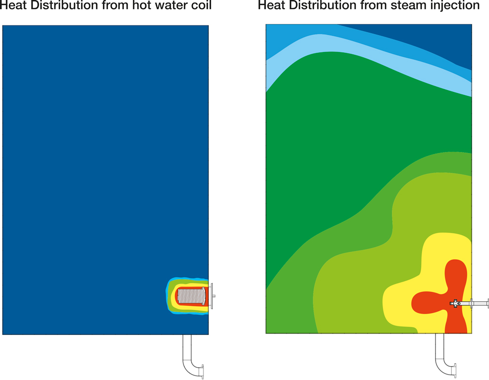
The figure illustrates the difference between heat distribution from a Hot Water Coil and a Steam Injection Lance. Injection of steam results in an efficient heat distribution. The oil emulsion works as an insulating layer on the heat surface of the coil, thus limiting heat distribution to the entire tank volume.
If the effectiveness of the coil is to increase significantly, the layer thickness must be reduced equivalently. This is only possible if we use heat exchangers with very small gaps between the plates. General circulation inside the tank will not influence heat transport so near the surface of the coil.
No measurements were done in a mixture of hydrocarbon and water. Since the resistance of the transferred heat is found alongside the film near the coil's surface, we assume that when the coil is contaminated with hydrocarbon heat transport will be much lower, even in an oil/water mixture. Using a hot water coil of this magnitude for tank heating will not work because the transferred effect in oil is not even close to satisfying NOFO's requirements.
Oil-fired or Electrical boiler
PARAT Halvorsen can deliver both electrical and oil-fired boiler alternatives as part of the integrated solution. There are advantages and disadvantages with both technologies, which is illustrated in the table below.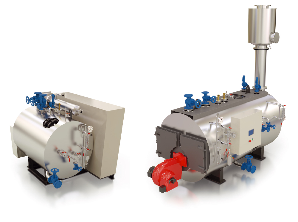
|
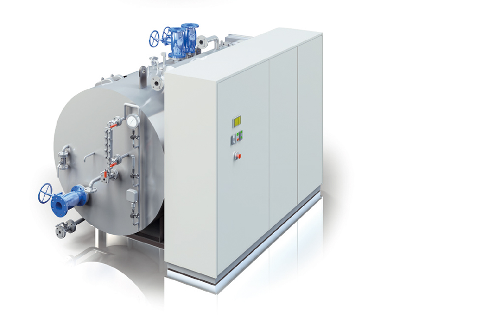
PARAT MEL-C, 1250kW, Electrical |
PARAT MSH, 1250kW, Oil-fired |
|
Electrical |
Oil-fired |
||
| + | - | + | - |
| Compact size | Requires sufficient power supply | High fuel efficiency | Size and weight |
| Very low turn down 1:100 | Lower overall fuel efficiency | Low electrical power consumption | Turn-down 1:3 |
| Minimal maintenance | Additional effect panel | Robust design | Maintenance |
| No need for flue gas ducting |
More cable routing in vessel |
Additional fuel tank required | |
| No need for additional fuel tank | |||
| No need for fuel supply arrangement | |||
Retrofit
For existing vessels that do not have a tank heating system installed, Parat Halvorsen can deliver complete retrofit packages. Either by replacing the existing hot water boiler with a new combined steam and hot water system, or with a containerized boiler system placed on deck.
More Information